Classification of Explosive Atmospheres (Hazardous Area - Zone Classification)
Potential explosive atmospheres are classified into
"Zones"
in order to ensure plant safety, select the correct electrical or mechanical equipment,
and apply appropriate explosion protection measures.
Hazardous area classification and the preparation of the Explosion Protection Document
are carried out in accordance with
EN IEC 60079-10-1
for gas/vapour atmospheres and
EN IEC 60079-10-2
for combustible dust atmospheres.
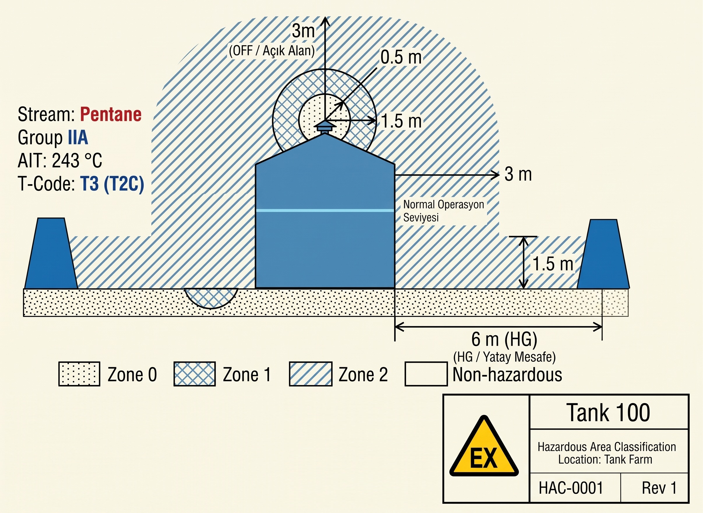
Example Diagram: Cross-sectional representation of Zone 0, Zone 1 and Zone 2
extents in a typical installation and filling area.
1. Explosive Atmospheres Caused by Gases, Vapours and Mists
Explosive atmospheres formed by flammable gases, vapours or mists mixed with air
are divided into three zones according to the frequency of occurrence
and the duration of the hazardous atmosphere:
-
ZONE 0:
An area in which an explosive gas atmosphere is
present continuously, for long periods or frequently
under normal operating conditions.
(Examples: the interiors of fuel tanks, reactors and evaporators).
Equipment Category to be Used: Category 1G (EPL Ga)
-
ZONE 1:
An area in which an explosive gas atmosphere is
likely to occur occasionally
during normal operation.
(Examples: filling openings, areas around sampling points and areas around pumps
where leakage may occur).
Equipment Category to be Used: Category 2G (EPL Gb) or higher
-
ZONE 2:
An area in which an explosive gas atmosphere is not expected to occur
during normal operation; however, if it occurs due to an accident,
malfunction or maintenance condition, it persists
only for a short period.
(Examples: the wider surroundings of flanges, valves and pipe connections).
Equipment Category to be Used: Category 3G (EPL Gc) or higher
2. Explosive Atmospheres Caused by Combustible Dust
Areas where combustible dust clouds suspended in air or hazardous dust layers
may occur are classified using a system parallel to that used for gas atmospheres:
-
ZONE 20:
An area in which a combustible dust cloud is present in the air continuously,
for long periods or frequently.
The interiors of dust silos or pneumatic conveying lines are typical examples.
Equipment Category to be Used: Category 1D Equipment (EPL Da)
-
ZONE 21:
An area in which a combustible dust cloud is likely to occur occasionally
during normal operation.
Areas around dust discharge or bagging points are typical examples.
Equipment Category to be Used: Category 2D Equipment (EPL Db) or higher
-
ZONE 22:
An area in which a combustible dust cloud is not expected during normal operation,
and if it occurs as a result of leakage, it persists only for a short period.
Equipment Category to be Used: Category 3D Equipment (EPL Dc) or higher
3. Standard Zone Drawing Representations
In engineering projects and explosion-risk maps, hazardous areas are represented
using internationally recognized
hatching patterns.
Typical zone patterns are shown below:
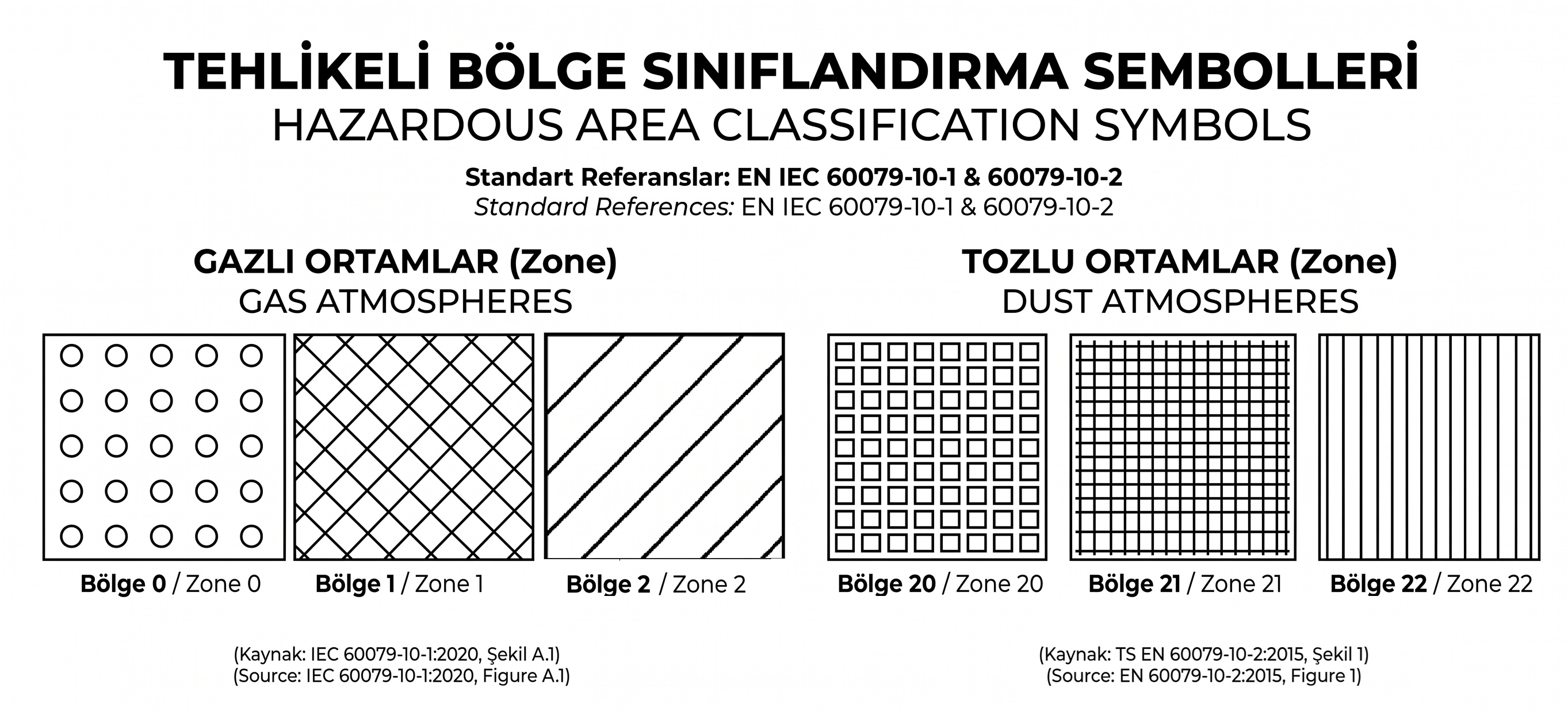
Gas & Vapour Hatching
-
Zone 0:
Cross-hatching lines (Grid/Diamond)
-
Zone 1:
Round/Circular patterns
-
Zone 2:
Single-direction diagonal lines
Dust Hatching
-
Zone 20:
Square block patterns
-
Zone 21:
Vertical straight lines
-
Zone 22:
Intersecting horizontal and vertical grid lines
Basic Assessment Steps (Hazardous Area Classification Methodology)
-
Identification of Sources of Release:
The locations where flammable substances may be released into the atmosphere
within the installation are identified.
-
Determination of the Grade of Release:
Based on the characteristics of the release, it is classified as
Continuous, Primary or Secondary.
-
Ventilation Analysis:
It is determined whether the area is outdoors, naturally ventilated
or provided with forced (mechanical) ventilation.
-
Determination of Zone Type and Zone Extent:
The physicochemical properties of the substance and the ventilation parameters
are evaluated in order to define and map the three-dimensional hazardous area.
